
Antennas and Probes
- LPD antennas up to 1000 MHz
- Near-field probes 790 MHz to 3 GHz
- Spherical antennas up to 100 MHz
- E field antennas up to 100 MHz
- H field antennas up to 30 MHz
- Isotropic receiving antennas up to 100 MHz
Measurement antennas are required for determining electric and magnetic field strengths exactly. They transfer radiated electromagnetic waves in free space to guided waves. Passive antennas can be used as transmit antennas to reverse the process. Bi-conical antennas and Log-Per-Dipole antennas are well suited for broadband and directed high frequency measurements. In the field of EMC they are used to find unwanted radiation of products, may it be in the measurement, communication, automotive, or consumer electronics industry. Using these types of antennas only polarized measurements are possible as they are sensitive to vertically polarized or horizontally polarized waves, respectively, depending on the orientation. Each type of antenna is applicable to a specific frequency range only. Horn antennas are designed for directed radiation required in RADAR systems and directional radio. Near field probes can be used to quickly identify electromagnetic aggressors on printed circuit boards.
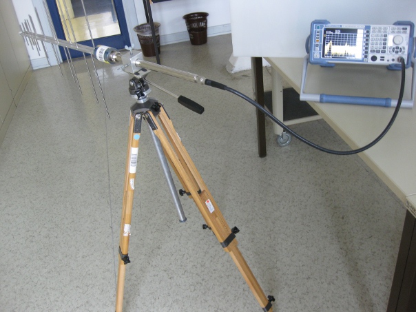
Measurement antennas differ in frequency range, beam angle, and directivity, as well as radiated power. For broad- or narrow-band measurements the corresponding antenna needs to be chosen before-hand. External stray signals deteriorate the measurements. To avoid those, measurements are typically conducted in a shielded measurement chamber. Typically, the antenna is placed inside the measured field on top of a non-conducting stand and connected to a spectrum analyzer by a microwave cable. To be able to repeat and validate the measurements, the antenna should be brought into a well defined position. During measurement every exposed antenna area extracts power from the incident fields. The resulting electrical signal is guided to the spectrum analyzer through the cable. For a correct evaluation of the signal, different quantities such as measurement bandwidth, sweep time, and detector type need to be configured in the spectrum analyzer. For emission of signals with a specific frequency and power, the antenna is connected to a signal generator and broad-band amplifier by a microwave cable. The emitted electromagnetic wave can be received by a testing antenna for purposes of inspection of calibration. This technique can be used to determine the EMC characteristics of an electric device.